Plate Rolling Workshop in Vyksa
Vyksa, 1897 - 1898
Engineer: V.G. Shukhov
Manufacturer: A. V. Bari Construction Company
Vyksa, 1897 - 1898
Engineer: V.G. Shukhov
Manufacturer: A. V. Bari Construction Company
MARCH - Technology module. ВА2 2019/20.
Balykina Sophia, Zaslavskaya Asya, Yumagulova Dina, Stepanyan Kristina, Stratu Tatiana, Tsydenov Sayan
Balykina Sophia, Zaslavskaya Asya, Yumagulova Dina, Stepanyan Kristina, Stratu Tatiana, Tsydenov Sayan
"Among the most interesting and original designs created by Shukhov is the structure at the Vyksa factory. For the first time in the world construction practice, Shukhov demonstrated the ability to assemble a spatial rectangular in a plan covering of double curvature from the single-type bar elements."
Engineer Kovelman G. M.
Engineer Kovelman G. M.
HISTORICAL CONTEXT
The success of lattice shell structures designed by V. G. Shukhov for the All-Russian Exhibition in Nizhny Novgorod in 1896, contributed to the development of relations between the A. V. Bari Construction Company, where Shukhov worked as chief engineer, and the Society of Vyksa Factory under the direction of A. I. Lessing.
As a result of this cooperation, several structures were built at Vyksa plant in 1897 - 1898 including spatial vaulted lattice shell structure for the sand drying workshop (cylindrical vault) and the doubly curved lattice shell of the plate rolling workshop building.
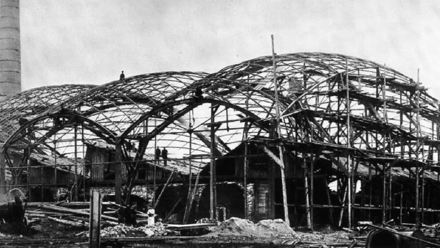
Plate rolling workshop at Vyksa plant during its construction, 1897; Historical photograph. (Personal archive of V. G. Shukhov)
STRUCTURE DESCRIPTION
The steel envelope of the hall consists of five lattice shell units with dimensions of 14.6 x 38.4 m in the plan that compose a single workshop space.
The main load-bearing elements of the structure of each section are three-hinged metal arched trusses with a span of 38.4 m, consisting of an upper belt, a lower belt, and braces between them.
They support a latticed shell structure, assembled from equal mutually intersecting Z-shaped profiles (80 x 40 mm), curved in the shape of circular arch segments. The lattice is attached to the trusses by means of gussets, forming a rigid spatial structure. On the profiles of the lattice, the purlins are laid, on which the roof covering made of sheet iron is attached (remained fragmentarily).
Ties are one of the most important structural elements. They are fixed in the transverse direction between the two adjacent main trusses and mitigate the thrust from the lattice envelope. Ties particularly well illustrate the principles of lightweight structures - the closure of forces within the structure itself.
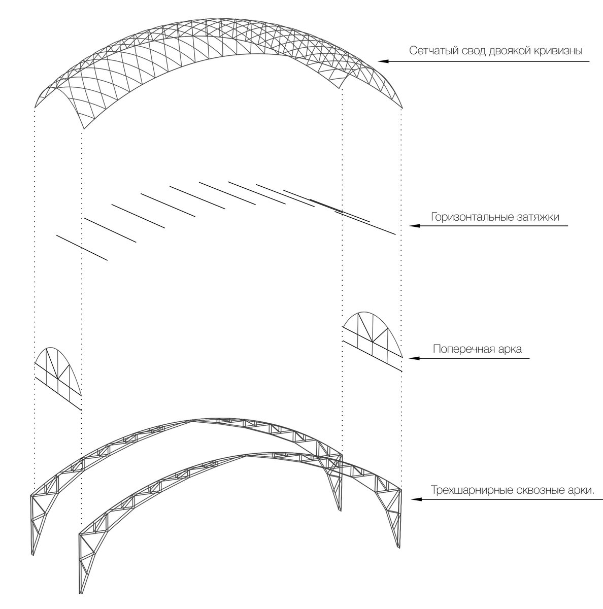
Explosion diagram of main structural elements

STRUCTURAL PRINCIPLE
The key prerequisite for the exceptional structural characteristics of the gridshell is its spatial curvature and the shape of both longitudinal and transverse edges - circular arches 1/5 to 1/6 in height of the span. With this ratio, the shape of the circular curve is as close as possible to the contour of the parabola (and the catenary line), which leads to the elimination of bending moments in the structure and the transfer of forces mainly within the cross-section (membrane action).
In his calculations, Shukhov also describes the curvature of the arches of the main support trusses (as well as the gridshell) as parabolic curves.
In production instead, the arches are described as circular segments with the same radius, which greatly facilitates their fabrication and replication.
The same principle is applied to the gridhsell created from a set of uniform, mutually intersecting segments of circular arches that are positioned at an equal distance by rotating them along the curve of the circumference of the upper girder of the main trusses (see diagram).
To reproduce that, the parametric model was built in Rhino/Grasshopper. First, two arches both in the longitudinal and transversal directions were modeled, then two central intersecting arches of the gridshell were built. Further, the remaining arches were positioned by rotating them with an angle of 4° between adjacent ones around the center of the upper girder circumference in both directions.
STRUCTURAL ANALYSIS
For structural analysis, we considered one span out of five, since the design principle is the same for all of them. The analysis was performed in the Rhino/Grasshoper environment using the Karamba3D module based on the finite element method (FEM).
DEAD WEIGHT
In order to see how the structure works under its own weight + uniformly distributed load from the roof covering, we took the values from Shukhov's calculations - 42.3 kg/m2. On the diagram of the internal stresses, one can see the work of the main structural elements: the top chord of large trusses is under tension, the lower - under compression. The hinge in the center of the upper chord eliminates the bending moment. The stresses in the gridshell are uniform, mainly axial, with a slight bending at the intersections. The thrust in the transverse direction is taken up by the steel ties.
SNOW LOAD
In order to simulate the real loading of the structure (more critical for vaulted shells), we assumed the uneven snow load, applied to one-half of the structure - 146.7 kg/m2. Under such loading, the left part of the structure deflects, and the right part of it bulges. The upper and lower chords of the large trusses bend, as is illustrated by the asymmetric compression and tension stresses in the chords. The gridshell still has predominantly axial forces without significant moments.
WIND LOAD
The wind load was calculated on the basis of modern requirements for the calculation of vaulted structures. The normative value of the wind impact is 38 kg/m2. The wind load was applied to the edge facade arches on both sides, with a coefficient of 0.8 on the windward side and -0.4 on the leeward side.
Based on our calculations, the following conclusions can be made:
a) the shape of the gridshell plays an important role in the performance of the structure - favorable axial stresses arise, contributing to the reduction of the cross-section and thus the weight of the elements.
b) the horizontal thrust from the vaulted is almost completely extinguished by the work of the ties, the vertical forces are transferred to the main trusses, which are also responsible for the stiffness of the structure under loads in the longitudinal direction.
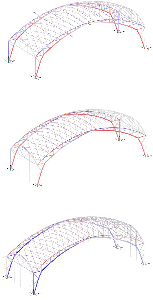
Diagrams of internal forces from a) dead weight, b) snow and c) wind loads
MODEL
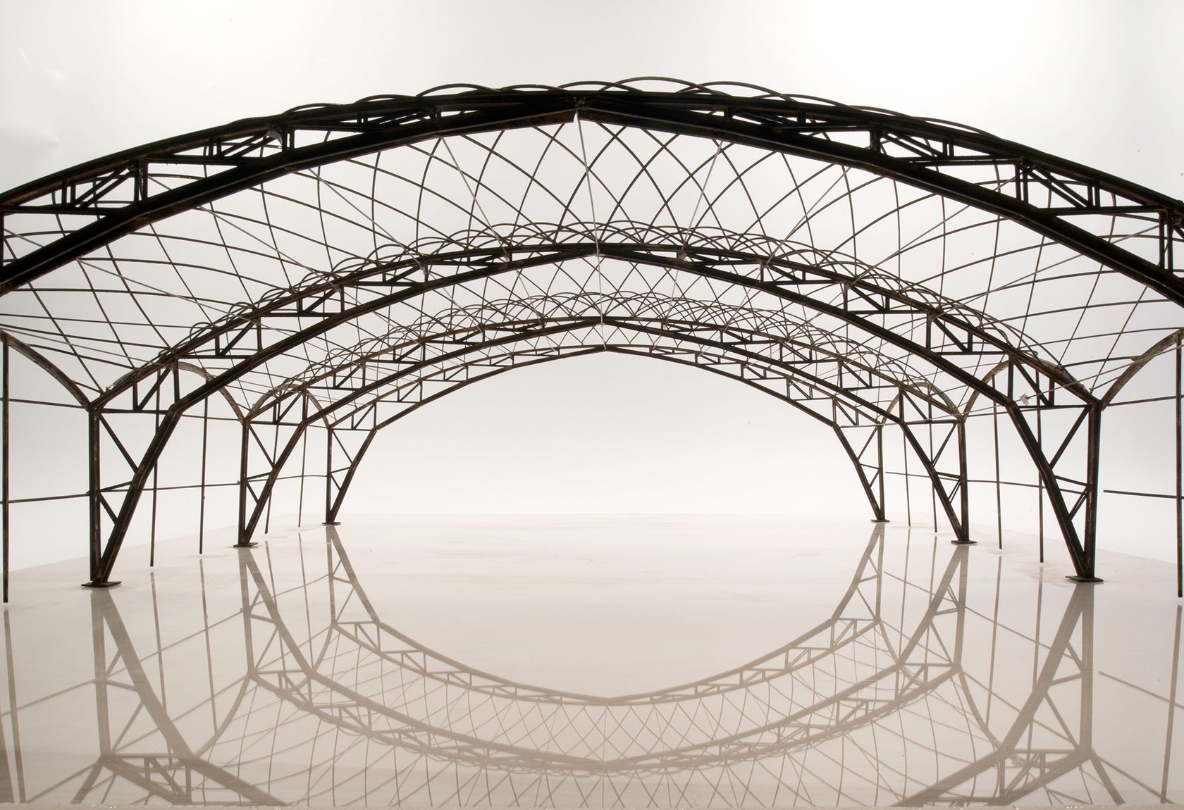
The physical model of the three sections of the Plate Rolling Workshop in Vyksa was created on a scale of 1:50 from the sheet brass, as well as from brass profiles with sections of 2 x 4 mm and 4 x 6 mm.
The production of the model consisted of four parts:
a) Laying out the 3D model into elements for laser cutting.
b) Laser cutting of the required elements, as well as the preparation of ready metal profiles for the production of the model
b) Assembly of the model. Soldering of individual elements.
c) Patination of the whole structure.
Photos of the model: Yurii Palmin
Gratitude
We express special gratitude to the A.V. Shchusev State Museum of Architecture and the curator of the exhibition “Shukhov. Formula of Architecture" to Mark Akopian for conducting an exhibition tour and providing archival materials and calculations of V.G. Shukhov, chief architect of GUM Vladimir Kamyshnikov, teacher of MGSU Yuri Yuzhakov, chief engineer of Metal Yapi Vasily Anopchenko and associate professor of the Russian State Humanitarian University Ilya Pechenkin for constructive criticism of the projects.
Sources
Archive of the Russian Academy of Sciences, F. 1508
Further reading
Shukhov V.G., Rafters. The search for rational types of rectilinear truss trusses and the theory of arch trusses. Russian Association of Printing and Publishing. Moscow. 1897
Shukhov V.G., Building mechanics. Selected Works; Edited by Academician A. Y. Ishlinsky. - Moscow: Science, 1977

© 2021 MARCH | Technology