4600 knots: bending-active
MARCH — Technology module. ВА2 2020-2021.
Ilya Dorokhin, Mila Kuzmina, Evgeniya Udalova, Maria Shvedko, Polina Arefieva, Katya Zarochentseva, Sonya Karamysheva
Teachers: D. Kovaleva, V. Grudsky, V. Veremchuk
Curator: I. Tomovich
Ilya Dorokhin, Mila Kuzmina, Evgeniya Udalova, Maria Shvedko, Polina Arefieva, Katya Zarochentseva, Sonya Karamysheva
Teachers: D. Kovaleva, V. Grudsky, V. Veremchuk
Curator: I. Tomovich
Bending active structures are structural systems comprising curved beam or shell elements whose geometry is based on elastic deformation from an initially straight or flat configuration. The spatial stiffness of such structures is usually due to the balance of tensile (internal) linear or spatial elements and an elastically deformed contour or multiple contours. The architectural potential of such structures has been investigated in this project.
PRINCIPLE OF WORK
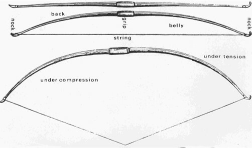
The most obvious demonstration of the bending active principle is provided by a human invention such as a bow (a firearm). Before the shot is fired, the shooter deflects the pre-tensioned bowstring by performing work with his hand. This work is used to add potential energy to the bending deformation of the bow's shoulder parts. When the shot is fired, the shooter releases the bowstring, allowing the shoulder parts to partially straighten and the bowstring to recover its straight shape, accelerating the arrow. This frees up part of the potential bending strain energy of the shoulders to the kinetic energy of the fast-flying arrow.
The most obvious demonstration of the bending active principle is provided by a human invention such as a bow (a firearm). Before the shot is fired, the shooter deflects the pre-tensioned bowstring by performing work with his hand. This work is used to add potential energy to the bending deformation of the bow's shoulder parts. When the shot is fired, the shooter releases the bowstring, allowing the shoulder parts to partially straighten and the bowstring to recover its straight shape, accelerating the arrow. This frees up part of the potential bending strain energy of the shoulders to the kinetic energy of the fast-flying arrow.
HISTORICAL PROTOTYPES IN FOLK ARCHITECTURE
In traditional architecture we can find examples of the use of the elastic properties of building materials as early as 3000 B.C. The Mudhif is a traditional building of the Ma'adans (inhabitants of the Iraqi marshes). Pre-harvested reeds are dried for 3 months. The thatch bundles are used to form a column by tying it with a bundle also made of reeds. The reeds are inserted into the ground at an inclined depth of one metre. They are then joined at the top to form an arch.
In traditional architecture we can find examples of the use of the elastic properties of building materials as early as 3000 B.C. The Mudhif is a traditional building of the Ma'adans (inhabitants of the Iraqi marshes). Pre-harvested reeds are dried for 3 months. The thatch bundles are used to form a column by tying it with a bundle also made of reeds. The reeds are inserted into the ground at an inclined depth of one metre. They are then joined at the top to form an arch.
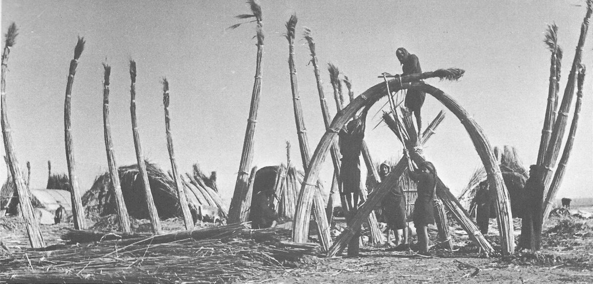
Mudhif during construction.
Bernard Rudofsky; “Architecture Without Architects."
Bernard Rudofsky; “Architecture Without Architects."
CONTEMPORARY ARCHITECTURAL APPLICATIONS
A modern example of this principle is the Multihalle pavilion in Mannheim. The Multihalle consists of two enclosures connected by a canopy. The entire structure has dimensions of 160 x 115 metres.
A complex and flexible wooden grid, preassembled from straight elements on the ground, was used for the double-curvature envelope. During erection, the grid was lifted from bottom to top using scaffolding supports. Once the grid reached the desired shape, the boundaries of the envelope were fixed with a concrete ring girder. The pins, which once allowed the mesh nodes to rotate freely, are tightened with knot bolts.
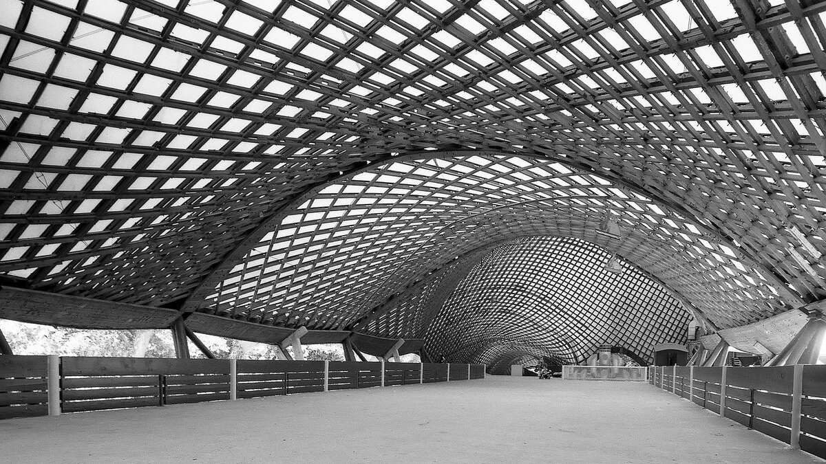
Multihalle in Mannheim
Carlfried Mutschler, Joachim Langner, Frei Otto (design), 1975 г.
Carlfried Mutschler, Joachim Langner, Frei Otto (design), 1975 г.
ABSTRACTION OF THE PRINCIPLE
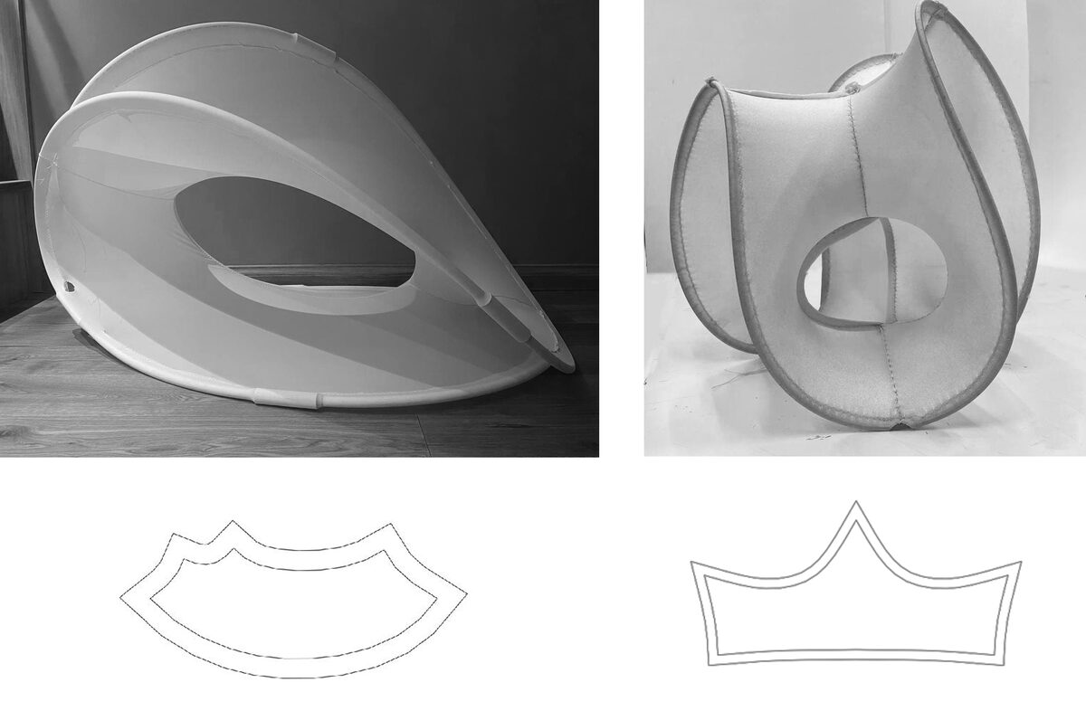
For the first physical models, the group used an elastic wire (cable, for example) and an elastic fabric (polyamide + elastane).
In the course of our experiments, we obtained the first physical model of a pringle (saddle surface) which further defined the course of our project. In our first physical layouts, we moved very intuitively: there was no understanding of the dimensions of the necessary cutouts, the length of the contour, the requirements for its degree of stiffness or softness.
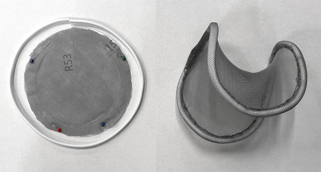
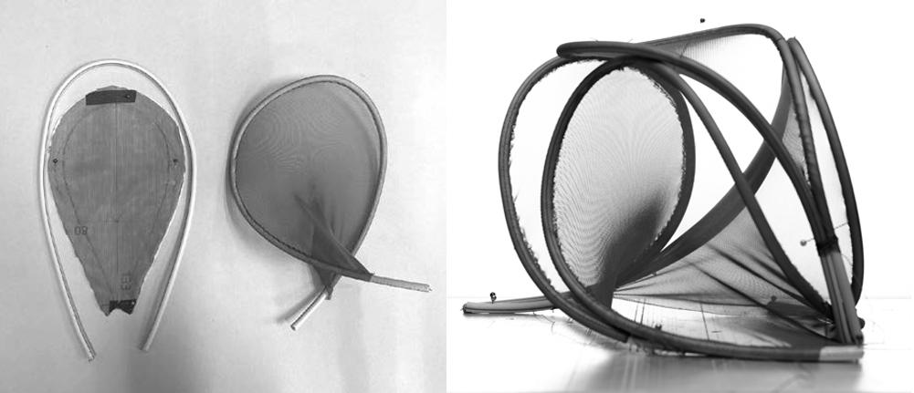
Gradually we figured out the balance of the bending active system, and began to complicate the shape with additional tightening. We also realised that contours can form different spatial patterns, where the fabric on the one hand works in a similar way to a membrane (stretching) and on the other hand 'assembles' the whole model into a stable state, balancing the elastic properties of the contour.
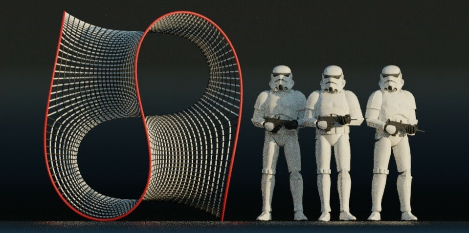
DIGITAL MODELLING
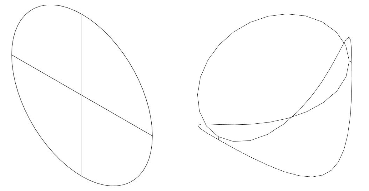
We repeated the principle of shaping physical models in a digital environment. To do this, we used the Kangaroo Physics plug-in in Rhino/Grasshopper and its ability to simulate the elastic deformation of a contour by compressing one or more strings attached to its ends. As the length of the string decreases, the contour, while retaining its elasticity, extends out of the plane and bends, taking the shape of the familiar saddle.
We repeated the principle of shaping physical models in a digital environment. To do this, we used the Kangaroo Physics plug-in in Rhino/Grasshopper and its ability to simulate the elastic deformation of a contour by compressing one or more strings attached to its ends. As the length of the string decreases, the contour, while retaining its elasticity, extends out of the plane and bends, taking the shape of the familiar saddle.
Digital shaping of bending-active structures in Kangaroo Physics
A similar result can be obtained by working with a meshed model instead of a linear one. The initial surface topology, which largely determines the final shape of the structure, is important. To do so, it is sufficient to topologically correctly model the future surface as separate but stitched together mesh planes, which when simulated and reduced in length by all mesh elements will result in a smooth surface and a similar contour curvature as in the previous example.
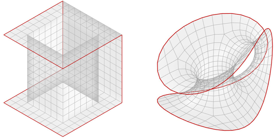
Digital shaping of bending-active structures in Kangaroo Physics
PATTERN MAKING
In the further stage of pattern development, we focused on working correctly with the patterns, as their cutting depends on the quality of the resulting surface, the shape of the contour curve, the evenness of the fabric stretching and the stability of the entire design. For this, we did some experiments with the patterns, gradually complicating their shape and topology. First, we assembled a model with two holes, resulting from four patterns, then we gradually increased the complexity of the geometry and settled on a threefold symmetric surface, consisting of 6 identical patterns.
Important criteria for the quality of the fnal surface are:
- the accuracy of the connection of the patterns to each other;
- The size reduction factor of the cutout during cutting.
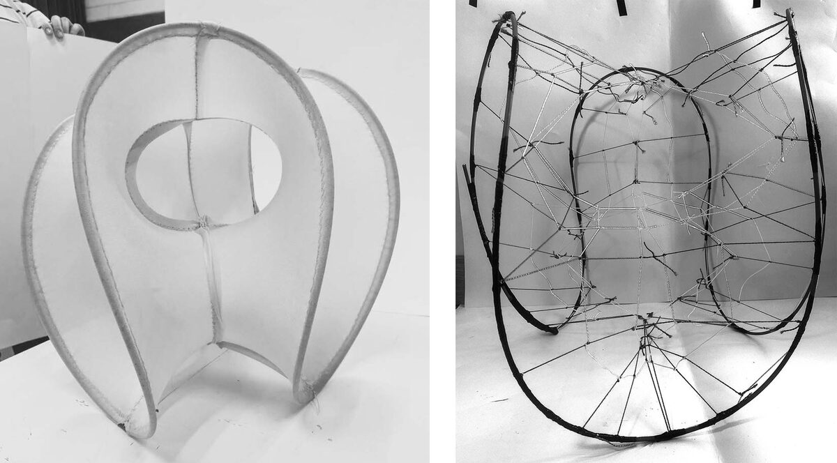
FROM FABRIC TO SPATIAL MESH
The alternative method of obtaining the surface of the structure in the form of a net is found to be more suitable. The rope mesh woven from the pattern behaves more predictably in the test layout compared to the fabric patterns. This approach allowed us to calculate the dimensions of the final design and material consumption more accurately.
The mesh is a stable element because the cord is fixed in knots. In this way, we were able to minimise the impact of relative elongation under load during the weaving stage of the mesh.
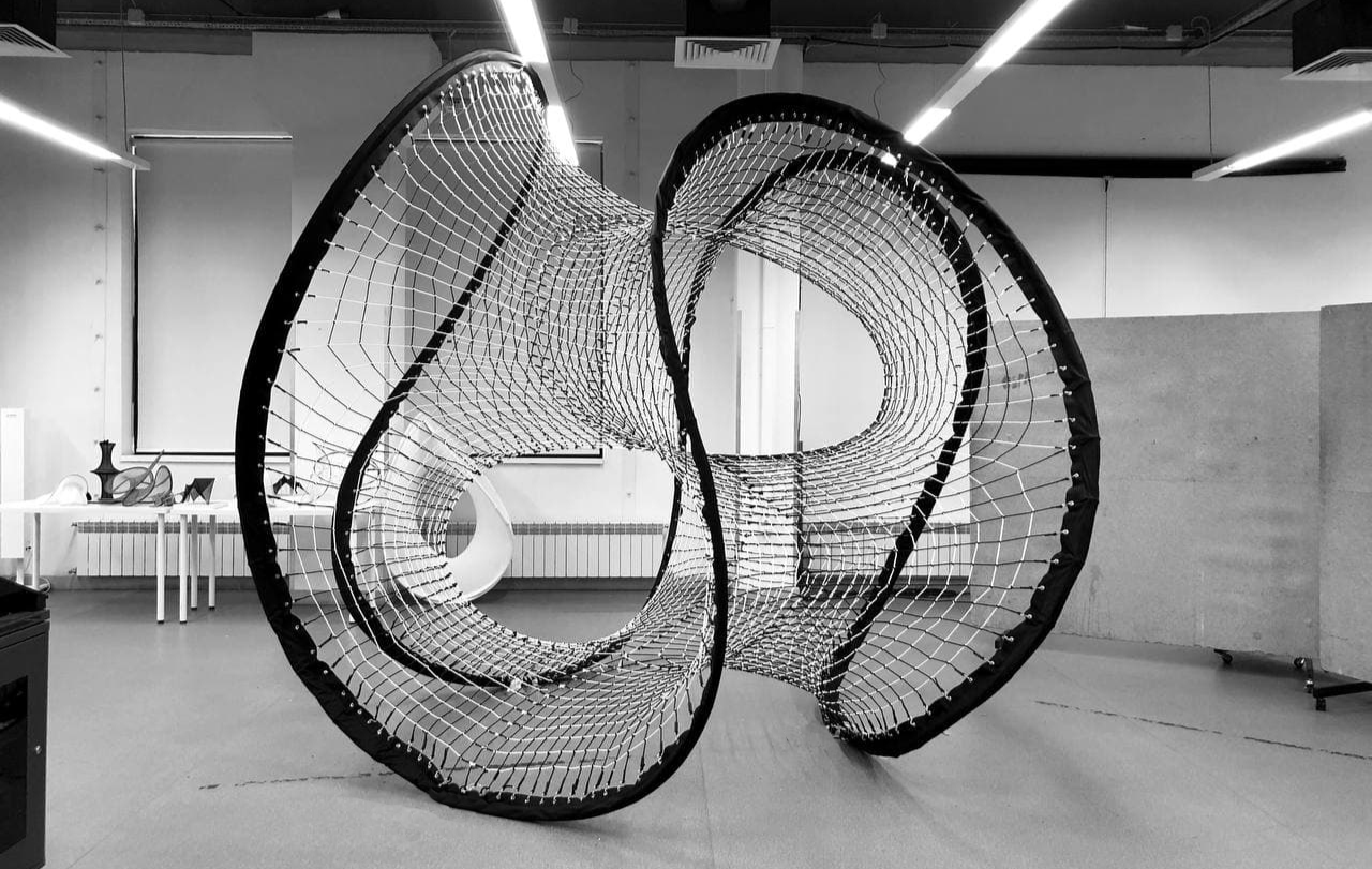
FINAL MODEL
The final design of the group is a spatial object that can be installed both outdoors and indoors (if the ceilings are high enough). It can be used
The final design of the group is a spatial object that can be installed both outdoors and indoors (if the ceilings are high enough). It can be used
as an art object, or serve the utilitarian function of being a recreational space for children.
MODELLING AND ANALYSIS OF THE FINAL STRUCTURE
The modelling of the structure for the preparation of the cutouts proceeds in the same way as in previous experiments: from construction of the correct topology to subsequent relaxation of the mesh and obtaining the final shape of the structure with all the necessary dimensions of the future cutouts. A verification calculation was also performed to determine the mesh stress and the bending stress in the contour.
The modelling of the structure for the preparation of the cutouts proceeds in the same way as in previous experiments: from construction of the correct topology to subsequent relaxation of the mesh and obtaining the final shape of the structure with all the necessary dimensions of the future cutouts. A verification calculation was also performed to determine the mesh stress and the bending stress in the contour.
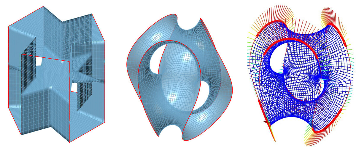
Finding the shape of a structure in Kangaroo Physics and analysis in K2Engineering
SELECTION OF MATERIALS AND SECTIONS
The selection of the material combination of the inner mesh and the contour is fundamental to the equilibrium of the entire structure. The selection of the contour stiffness is one of the main problems, because on the one hand the bending stress must be sufficient to stretch the mesh and on the other hand not be too great so that the 'hand-assembly' of the structure remains possible and safe. We used cords of polypropylene multi-filament yarns as the main construction material, and for the outline we used fibreglass bars connected to each other with clamps.
The selection of the material combination of the inner mesh and the contour is fundamental to the equilibrium of the entire structure. The selection of the contour stiffness is one of the main problems, because on the one hand the bending stress must be sufficient to stretch the mesh and on the other hand not be too great so that the 'hand-assembly' of the structure remains possible and safe. We used cords of polypropylene multi-filament yarns as the main construction material, and for the outline we used fibreglass bars connected to each other with clamps.
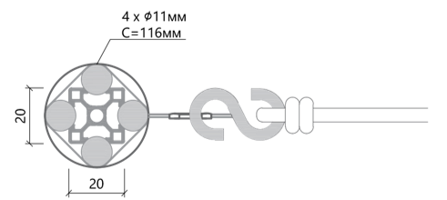
Nail mesh attachment unit to the contour
WAVING THE NETTING
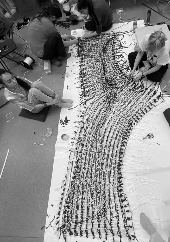
One of the most time-consuming processes was the process of weaving the net.
Having printed out a huge sized pattern and bought a small amount of rope, we started knotting. At first the work was incredibly difficult, knotting such a large quantity was the first time we had ever done it, and most likely the last.
We faced our first problems almost immediately. When we were finishing the first horizontal lines we noticed that we were too short of ropes and that it would not be possible to tie one net to the other. So we had to untie everything we had braided and re-braid it, saving a lot of rope for the free edge. So we had 6 parts of our object, and then began the process of tying the parts together. Here, too, was not without problems. Our object is three-dimensional in space, which means that it is not so easy to join it on the floor, and we had to twist all the connected parts to be able to weave the last parts. We began to attach the hooks and when they were twisted they got caught. We solved this problem by using scotch tape to wrap the hooks around the tape.
At the initial stage, we developed a knot - a double loop. A net of ropes with a similar knot, as you can see in the photo, can hold a man's weight. During the process we encountered a number of problems, for instance, it became apparent that the black and white threads have different stretch, so in order to reduce the error in the pattern we put extra length into the outline. All the edges are heat shrink-wrapped. The mesh is attached to the outline using S-hooks, the outline itself is tucked into a casing in which the eyelets for the hooks are punched in.
THE STRUCTURE ASSEMBLY
In the test assembly, the contour was not rigid enough and we had to reinforce it by increasing the cross-sectional area by inserting additional aluminium profiles.
In the test assembly, the contour was not rigid enough and we had to reinforce it by increasing the cross-sectional area by inserting additional aluminium profiles.
At 30cm spacing, 3cm pieces of V20x20LX aluminium structural section were installed. The number of GRP bars was increased to 4. At the points where the profile pieces were installed, the bars were tightened with metal clamps. The design of the connection unit remains otherwise unchanged.
CONCLUSION
Bending active systems express one of the principles of lightweight construction - equilibrium by combining two opposing types of loading: a tensile inner diaphragm and an elastically curved outer contour.
Bending active systems express one of the principles of lightweight construction - equilibrium by combining two opposing types of loading: a tensile inner diaphragm and an elastically curved outer contour.
By correctly calculating the pre-stressing of the membrane and the stiffness of the circuit, a spatially stiff yet extremely light construction can be achieved.