Tensegrity bridge
MARCH — Technology module. ВА2 2020-2021.
Alexandra Bartosh, Ekaterina Gindia, Alexander Zaichko, Maria Matrosova, Maria Novikova, Ksenia Shubenko
Tutors: D. Kovaleva, V. Grudsky, V. Veremchuk
Curator: I. Tomovic
Alexandra Bartosh, Ekaterina Gindia, Alexander Zaichko, Maria Matrosova, Maria Novikova, Ksenia Shubenko
Tutors: D. Kovaleva, V. Grudsky, V. Veremchuk
Curator: I. Tomovic
Tensegrity systems illustrate a key principle of lightweight construction - the absence of bending moments: all elements are loaded evenly and work either in tension or compression. Tensegrity can be described as an ideal construction because it uses the least amount of material. However, they are seldom used in construction due to the complexity of their design and the limitations of geometry, which impedes their functionality. It is the search for a balance between the principle of Tensegrity and its application to the specific function of the bridge that this project is devoted to.
WHAT IS TENSEGRITY
Tensegrity (from tensional integrity) is the structural principle for assemblies made of rods and cables, in which rods work in compression and cables in tension. The rods are not in contact with each other but hang in space and their relative position is fixed by the tensioned cables, as a result neither of the rods works under bending.
The term tensegrity was coined by scientist and architect Richard Buckminster Fuller. In Russia, structures of similar principle were promoted immediately after the October Revolution by the Petrograd artist, constructivist Karl Johansson (1890-1929).
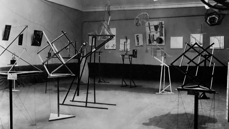
Tensioned Models at the Exhibition of the Members of the OBMOHU (Society of Young Artists), 1921.
HISTORICAL PROTOTYPES OF TENSEGRITY SYSTEMS
The historical prototypes of Tensegrity systems are truss structures where the individual struts take different types of stress: tension or compression. During the 19th century, with the development of metal, new types of structures emerged: Polonceau trusses and arched trusses with struts, in which the tensile struts were replaced by thin rods and strings, which greatly lightened the weight of the structure.
The structures of the Baron Stieglitz Museum in St Petersburg (see materials) and the Machine Hall at the Nizhny Novgorod exhibition (see materials on the example of GUM) were chosen to investigate historical analogues as the most expressive illustrations of the principle of tensegrity.
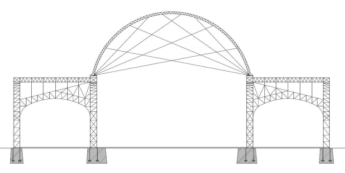
Cross-section of the Machine Hall at the Exhibition in Nizhny Novgorod, 1896.
D. Andreeva
D. Andreeva
HOW TENSEGRITY WORKS
Classical tensegrity structures are rod and rope structures in which the rods work in compression and the ropes work in tension. The most important condition for such a structure is a state of stable tension-compression equilibrium, depending on the geometric characteristics of the model, the location of the compressive rods and tensile ropes, as well as the presence of prestressing. A distinction is made between rod and membrane (surface) tensegrity. In the latter, the rods still work in compression, but are embedded in an elastic membrane that works in tension.
Classical tensegrity structures are rod and rope structures in which the rods work in compression and the ropes work in tension. The most important condition for such a structure is a state of stable tension-compression equilibrium, depending on the geometric characteristics of the model, the location of the compressive rods and tensile ropes, as well as the presence of prestressing. A distinction is made between rod and membrane (surface) tensegrity. In the latter, the rods still work in compression, but are embedded in an elastic membrane that works in tension.
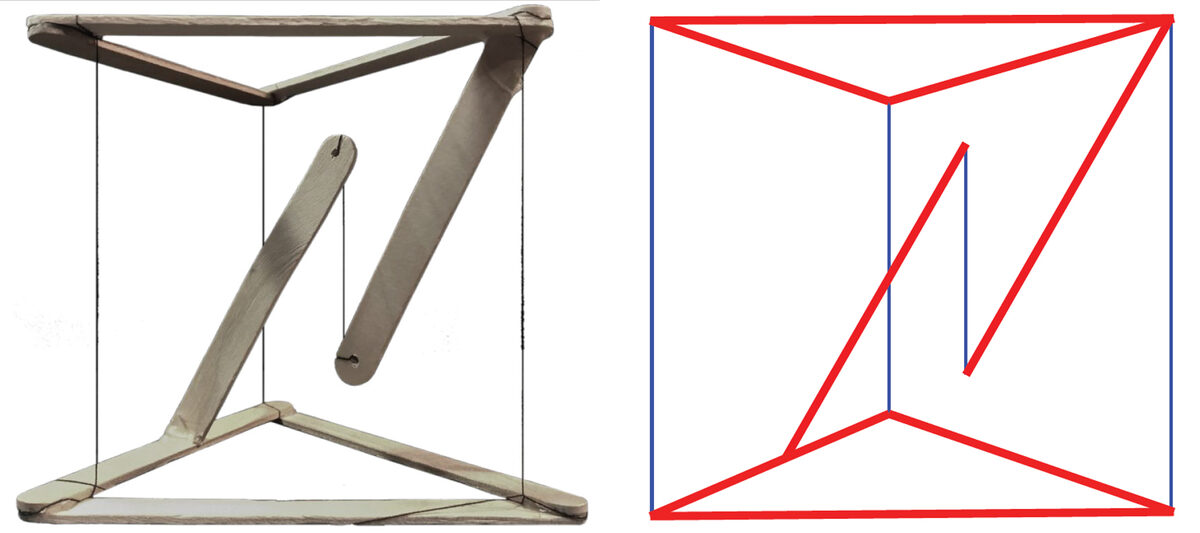
The core model of Tensegrity. Schematic diagram of how the individual elements work:
red - compression, blue - stretching.
А. Zaichko
red - compression, blue - stretching.
А. Zaichko
Spatial tensegrity consists of minimal, discontinuous non-contiguous linear elements connected by a continuous tensile surface element.
To control the final shape of the structure, the pattern of compressive elements serves solely as a means of prestressing and transferring loads to the tensile elements. In this experiment, it was important to find the optimum structure and logic that would stretch the fabric evenly, hold the desired shape and overlap the space.
To control the final shape of the structure, the pattern of compressive elements serves solely as a means of prestressing and transferring loads to the tensile elements. In this experiment, it was important to find the optimum structure and logic that would stretch the fabric evenly, hold the desired shape and overlap the space.
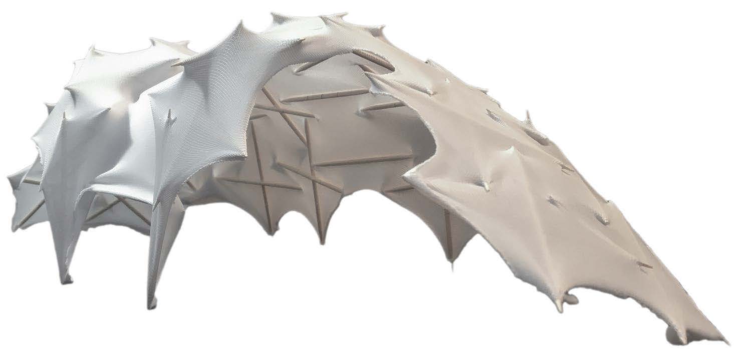
The Surface Tensegrity Model
A. Zaichko
A. Zaichko
DIGITAL MODELLING OF TENSEGRITY
Equilibrium of tensegrity systems can be found in a digital environment by simulating physical processes using the Kangaroo 3D plug-in in the Rhino/Grasshopper environment. The system elements (rods and cables) are assigned different stiffness parameters and an iterative process finds the equilibrium state of the system, leading to the final configuration.
Equilibrium of tensegrity systems can be found in a digital environment by simulating physical processes using the Kangaroo 3D plug-in in the Rhino/Grasshopper environment. The system elements (rods and cables) are assigned different stiffness parameters and an iterative process finds the equilibrium state of the system, leading to the final configuration.
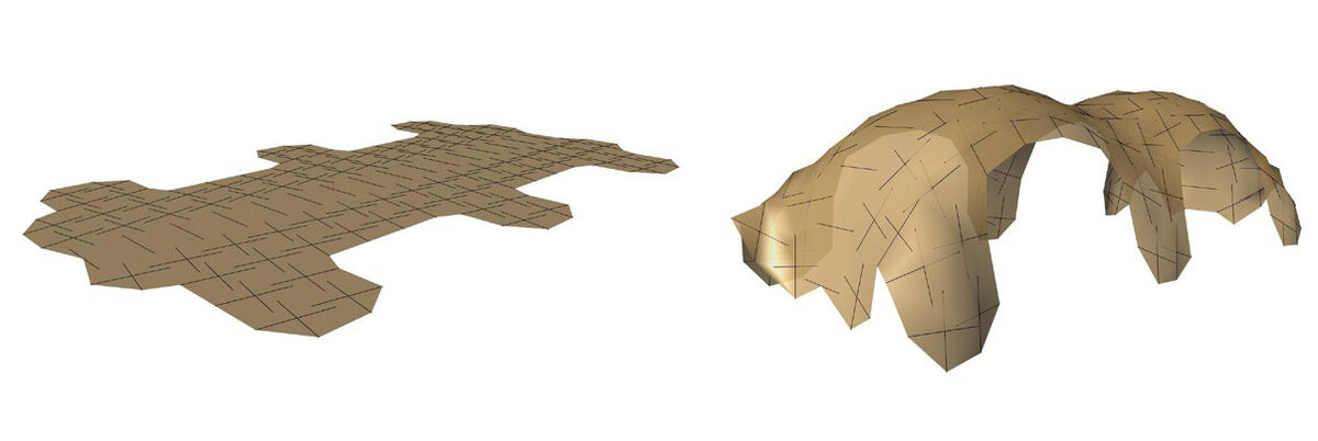
The first and final geometry of the Tensegrity model after simulation in Kangaroo 3D
Author: A. Zaichko
Author: A. Zaichko
APPROACH TO FINAL DESIGN
The search for the shape of the future bridge structure began with the construction of simple rod-rope models, investigating their geometric configurations and equilibrium conditions. To do this, we worked with the numerical models in Grasshopper, setting the initial geometry, assigning compressive and tensile elements, and then finding the position of the system elements that bring it into equilibrium in Kangaroo (Rhino/Grasshopper plug-in). After that, we calculated the forces in the individual elements using the Karamba 3D (structural analysis plug-in for Grasshopper) and assigned the required cross-sections. As a verification of the numerical models, we created physical mock-ups based on the geometric properties obtained from Kangaroo in order to better understand the performance of the structure and to think about the necessary structural components for such a system.
The search for the shape of the future bridge structure began with the construction of simple rod-rope models, investigating their geometric configurations and equilibrium conditions. To do this, we worked with the numerical models in Grasshopper, setting the initial geometry, assigning compressive and tensile elements, and then finding the position of the system elements that bring it into equilibrium in Kangaroo (Rhino/Grasshopper plug-in). After that, we calculated the forces in the individual elements using the Karamba 3D (structural analysis plug-in for Grasshopper) and assigned the required cross-sections. As a verification of the numerical models, we created physical mock-ups based on the geometric properties obtained from Kangaroo in order to better understand the performance of the structure and to think about the necessary structural components for such a system.
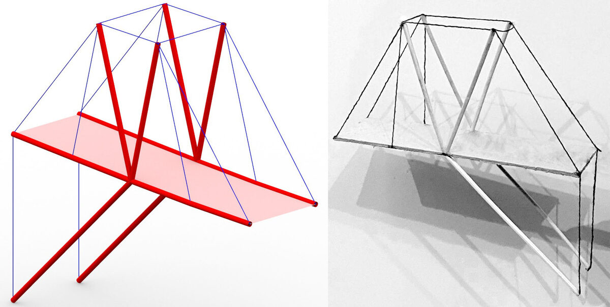
Digital and physical model of a cantilever consisting of compressed struts and stretched cables
DEVELOPMENT OF THE FINAL DESIGN SOLUTION
The development of the final design represented one of the most challenging periods of the group project. The shape underwent a huge number of changes. The main feature of the Tensegrity system is the lack of rigid connections between the compressive elements, so it was necessary to design a balanced system where all elements would be articulated and yet not interfere with the bridge deck. This was partly achieved by incorporating the deck into the design, where it acted as a longitudinal stiffening element. Also interesting was the relocating the top cables stabilising the vertical rods under the deck, thus freeing up the passage spaces completely, making the bridge fully functional.
The development of the final design represented one of the most challenging periods of the group project. The shape underwent a huge number of changes. The main feature of the Tensegrity system is the lack of rigid connections between the compressive elements, so it was necessary to design a balanced system where all elements would be articulated and yet not interfere with the bridge deck. This was partly achieved by incorporating the deck into the design, where it acted as a longitudinal stiffening element. Also interesting was the relocating the top cables stabilising the vertical rods under the deck, thus freeing up the passage spaces completely, making the bridge fully functional.
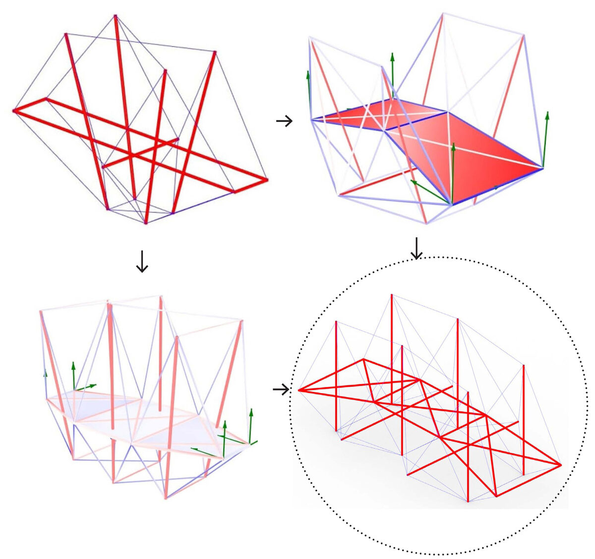
Development of the bridge design
DESCRIPTION OF FINAL DESIGN
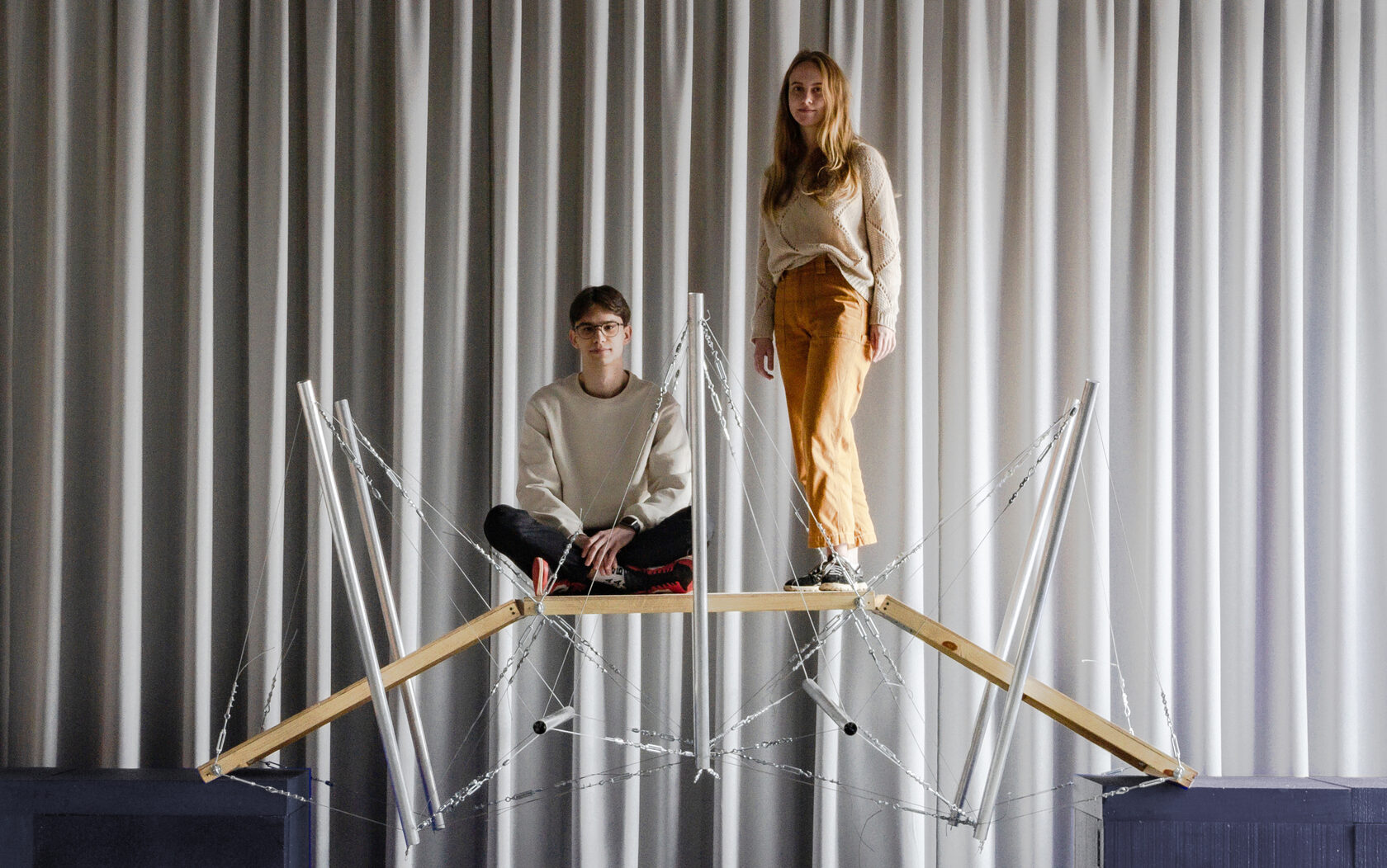
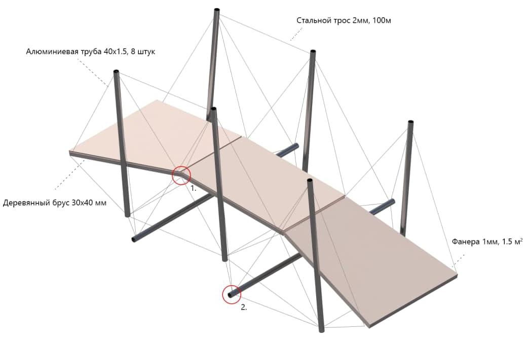
The bridge consists of three main elements: the span, the rods and the cables.
The dimensions of the structure are: 3 m x 1 m x 1.5 m (h) with anchor points at the beginning of the sides of the deck. Weight of the structure: 30 kg. The deck is made up of three parts connected by a hinged joint, as the deck is mobile due to the forces and cannot be rigidly connected.
The design was analysed in Karamba 3D, which revealed the correct operation of all structural elements when prestressed.
A cross-section optimiser showed that the minimum diameter of 1.5 mm thick pipe should be 3 cm. The strength of a long rod, at L=1560, and d=40 was 114 Pa. The cable was 2 mm thick, which sustained the applied forces and the optimiser without any problems.
PRODUCTION AND ASSEMBLY
The production and assembly of the structure went beyond all expectations. Even with a clear structure and joints it turned out to have many problems, both small and large. The main ones were the insufficient initial number of tighteners per cable (there was one, became two), trying to combine several cables to reduce the number of turnbuckles, which would simplify cable tensioning, and improve the appearance of the design. The first problem came up quickly, and was solved in the same way. The second, on the other hand, did not balance the design, which led to a subsequent redesign of each cable.
The production and assembly of the structure went beyond all expectations. Even with a clear structure and joints it turned out to have many problems, both small and large. The main ones were the insufficient initial number of tighteners per cable (there was one, became two), trying to combine several cables to reduce the number of turnbuckles, which would simplify cable tensioning, and improve the appearance of the design. The first problem came up quickly, and was solved in the same way. The second, on the other hand, did not balance the design, which led to a subsequent redesign of each cable.
An important task was to match the length of each cable to the final geometry and thread length of the turnbuckle. A bigger problem, however, was the insufficient cross-section diameter of the initial screw, which was 5 mm, which resulted in a trivial breakage when the entire structure was finally tensioned.
In the subsequent assembly stage, however, all the errors were corrected, and all that was left to do was to simultaneously tension all the cables and bring the structure into a position of equilibrium.