Geodesic dome at Carl Zeiss optical works
Jena, 1913 - 1924
Engineer: Walter Bauersfeld
Manufacturer: Carl Zeiss optical works
Jena, 1913 - 1924
Engineer: Walter Bauersfeld
Manufacturer: Carl Zeiss optical works
MARCH - Technology module. ВА2 2019/20.
Andrey Astakhov, Fedor Bolshakov, Alexandra Gavrilova, Sofia Dobychina, Victoria Denisova, Anna-Maria Stepanova
Andrey Astakhov, Fedor Bolshakov, Alexandra Gavrilova, Sofia Dobychina, Victoria Denisova, Anna-Maria Stepanova
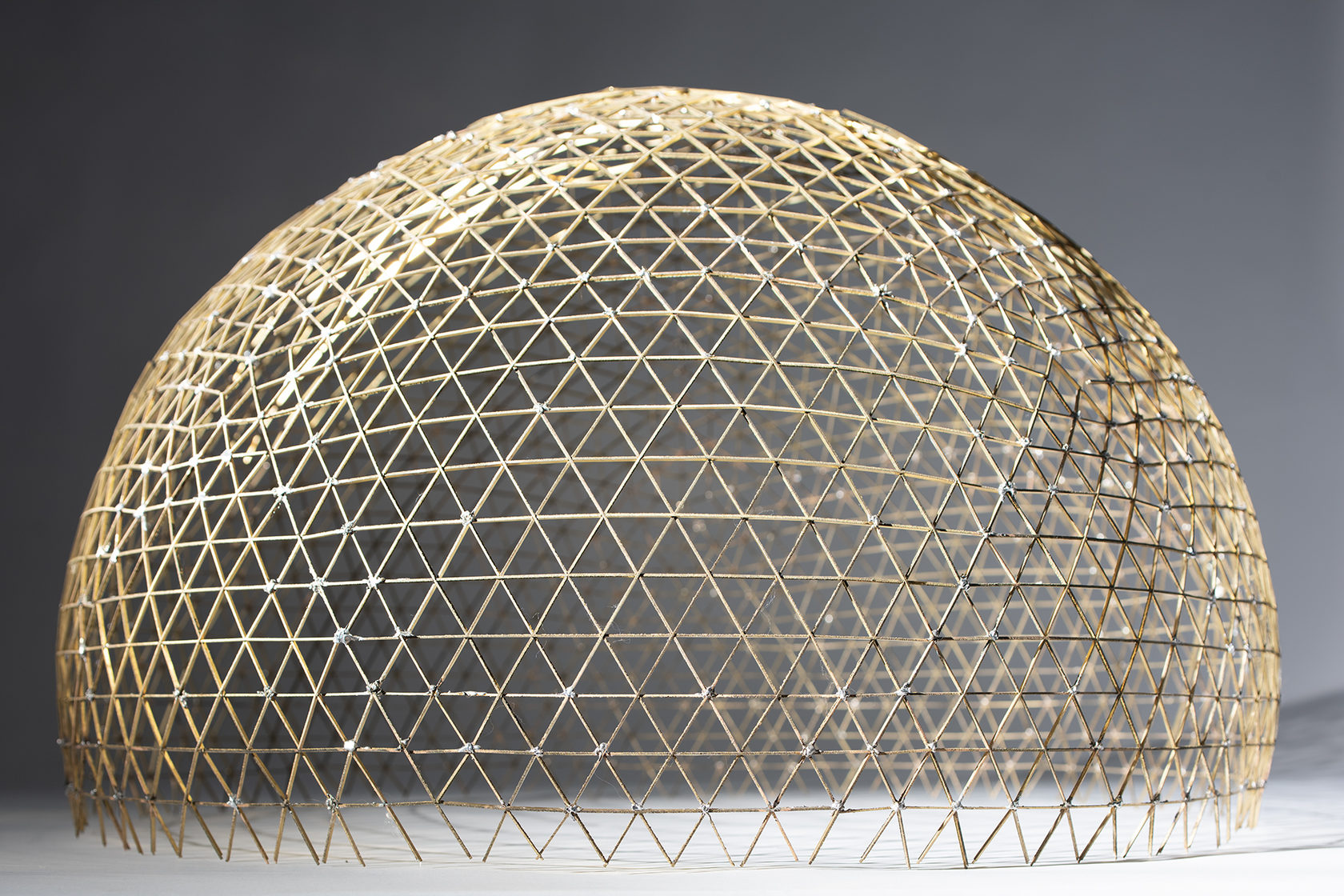
Steel geodesic lattice dome with a diameter of 18 m, erected on the roof of the Carl Zeiss optical factory in Jena in 1924, is the world's first geodesic dome, anticipating Fuller's domes by 30 years. During the study, we examined the structure in terms of its role in the history of domes and membrane shells, got acquainted with its geometric and structural, and construction principles, and built a physical model in 1:25 scale from laser-cut brass elements.
CONTEXT
The geodesic dome was designed in 1918-24 and built on the roof of the optical-mechanical plant in Jena, founded as a workshop for the production of precision optics by the German inventor Carl Zeiss.
Plant engineer Walter Bauersfeld was in charge of the project and also the author of the idea of the projection planetarium, as a system consisting of a mutually complementary projection device and a spherical projection screen (dome).
The dome was assembled from hundreds of 20 x 8 mm rectangular steel rods and subsequently sprayed with concrete to create an ideal spherical projection screen. The weight-to-span ratio of the domed shell became revolutionary, and, according to calculations, as the span increased, the construction of such domes became even more profitable.
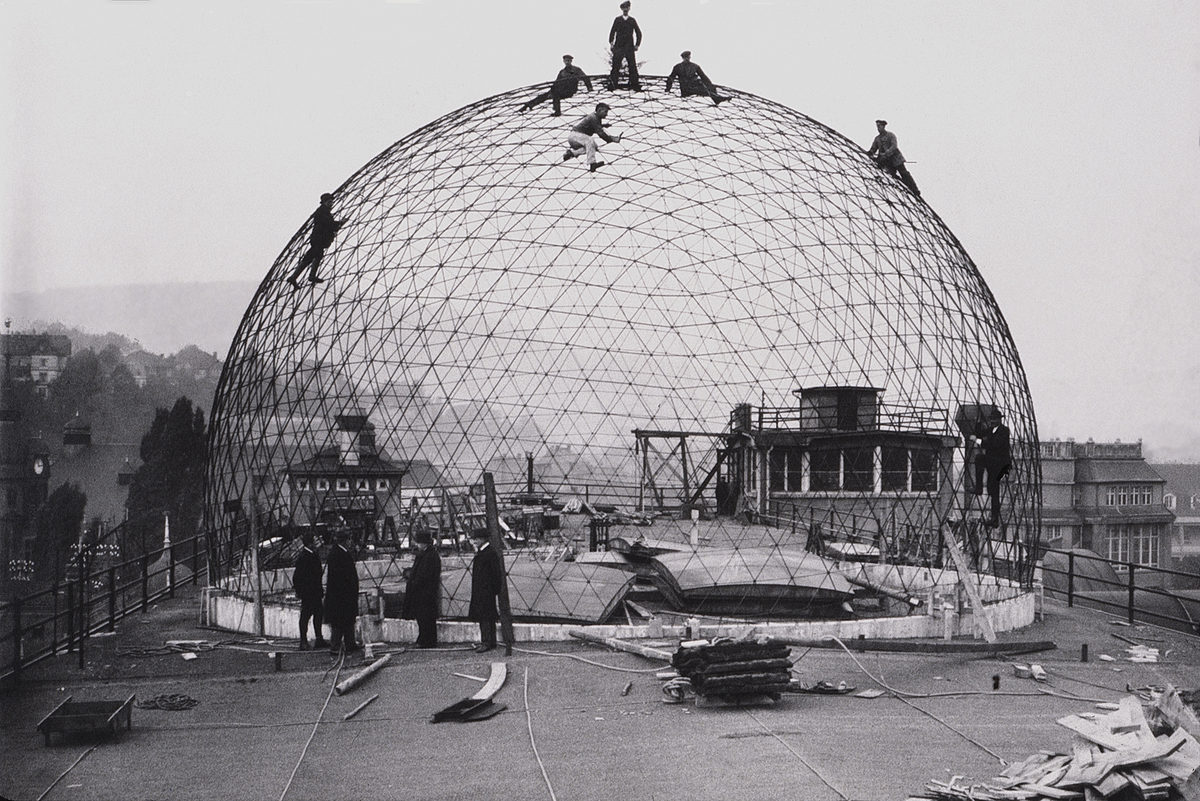
Assembling the geodesic dome on the roof of the Carl Zeiss factory, 1922 Archive of the Institute of Lightweight Structures (ILEK)
EVOLUTION OF SPATIAL DOMES
In 1866, the German engineer Johann Wilhelm Schwedler first proposed to design and analyze metal domes as spatial structures. Unlike ribbed domes, calculated as planar systems along meridional sections, Schwedler's dome is a spatial statically determined system assembled from the meridional, ring, and diagonal elements forming a rigid (triangulated) frame.
The new system significantly reduced the weight of the structure (up to 30%), simplified assembly, and made it possible to significantly increase the spans (up to 62m). Schwedler's domes were very popular both in Europe and in Russia until the beginning of the 20th century.
In the early stages of the development of spatial structures (Schwedler and Feppl systems),
the domes had a centrally symmetric structure, which led to an increase in the density of elements in the upper central zone and an uneven distribution of material.
In the sectorial-mesh domes, a more uniform division into elements was achieved by dividing the surface into 8 sectors, consisting of horizontal and diagonal struts. Finally, the pinnacle of the development of mesh dome structures was the geodesic dome, invented by Walter Bauersfeld during the creation of the first planetarium projection sphere. Unlike previous systems, the principle of its construction is based on the geodesic subdivision of the sphere and can only be used to create ideal spherical domes.
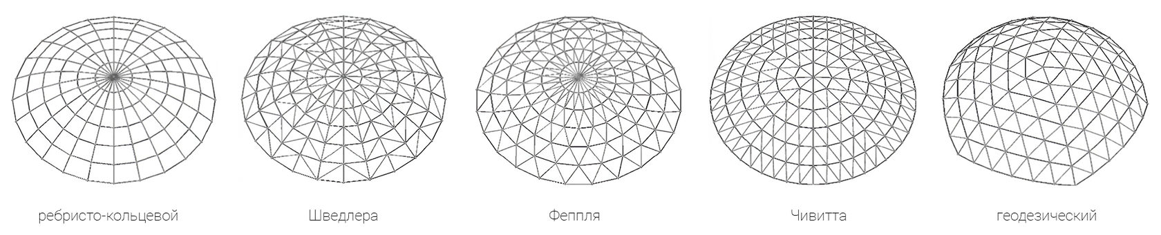
Dome types. Source: Yan et al., Mechanism of coupled instability of single-layer reticulated domes, 2016
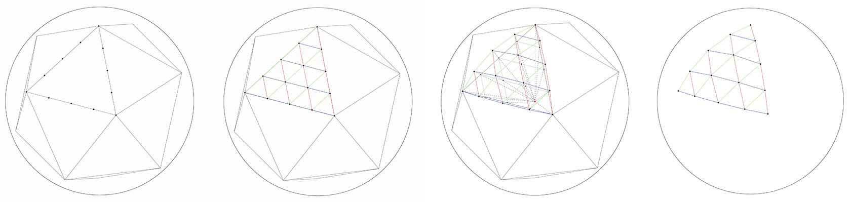
Conspruction of geodesic sphere by projection of the icosahedron
STRUCTURAL PRINCIPLE
The structure of the dome is obtained by subdivision of a spherical segment into triangles by means of the projection of icosahedron.
First, an icosahedron whose vertices lie on the surface of the sphere is inscribed into the desired sphere. Then each face (triangle) of the icosahedron is divided into equal parts. The intersection points of the faces, the vertices of the new triangles are projected onto the surface of the sphere. The projected points are connected by lines - obtaining projected triangles. The procedure is repeated until the required number of triangles/necessary edge length is reached.
To create a digital model of the dome, a parametric model was made in Rhino / Grasshopper, including the algorithm described above.
Note:
Projected triangles will inevitably all have different edge lengths and angles. The shortest faces (463 mm) are located at the nodes of the connection of the vertices of the sought triangles, the longest faces (661 mm) - in the center. The lengths of the elements were determined mathematically by Walter Bauersfeld and were manufactured in the factory with an accuracy of 1:10.000 of the length of the element, which was an unprecedented level of technical equipment and quality for the construction industry at that time.
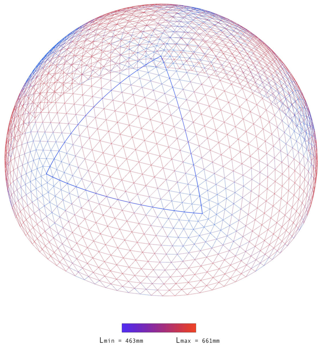
parametric model showing the variation of edge lengths of the elements in the geodesic dome
STRUCTURAL ANALYSIS
After creating a parametric model, the analysis of the structure was performed in Karamba 3D to check how it works under various loads and how its spatial rigidity is ensured.
Snow loads
For the calculation, the standard value of the snow load for Jena (similar to Berlin) located on the North German plateau was taken, which is 0.85 kN/m2.
The intensity of the snow load on the surface of the dome is usually taken according to the law p = p0 cos (φ), where p0 is the uniformly distributed load over the projection of the surface onto the horizontal plane.
The ring force changes sign at φ = 45°.
The stress diagram illustrates this principle, confirming the theoretical data: indeed, in the upper part of the dome, all elements are subject to compression, while tensile stresses arise in the ring (horizontal) elements in the lower zone.
The maximum deformation is 7 mm.
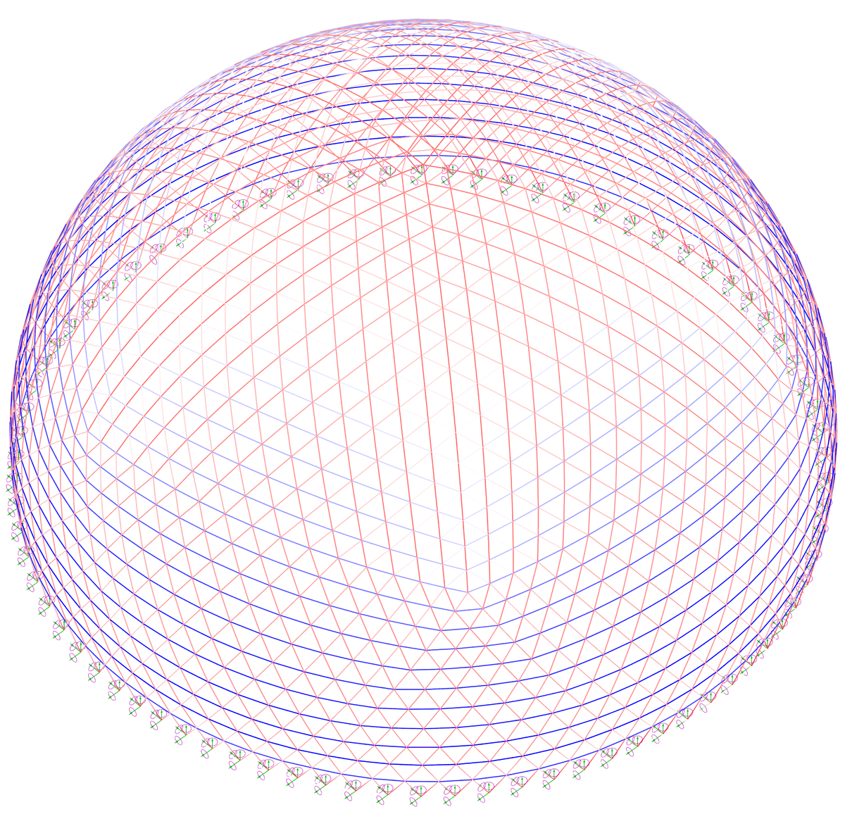
Stress diagram of the dome under snow load. Karamba3D
Wind loads
The forces from the wind load according to the literature are determined approximately by replacing the actual wind pressure with the sum of two formulas:
symmetric diagram:
W1 = W0 cos * 2φ,
and skew-symmetric diagram:
W2 = 0.5W0 sin * 2φ sin * 2φ,
where W0 is the velocity of wind pressure.
That is, according to the formula: W = W1 + W2
The standard wind load value for Jena, as well as for Berlin, is W0 = 0.39 kN/m2.
The stress diagram from wind load shows that only a small part of the dome is subject to inward deformation on the windward side. The rest of the dome is subject to bulging outward, so-called "suction". As a result, tensile stresses arise in a significant part of the structure.
The maximum deformation is 7.2 mm.
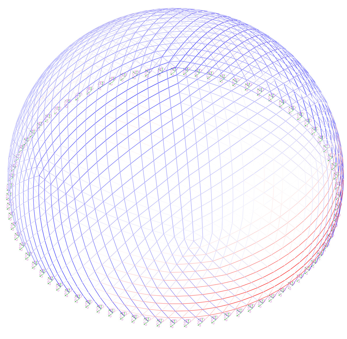
Stress diagram of the dome under wind load. Karamba3D
MODEL
Photos of the model: Yurii Palmin
Gratitude
We express special gratitude to the A.V. Shchusev State Museum of Architecture and the curator of the exhibition “Shukhov. Formula of Architecture" to Mark Akopian for conducting an exhibition tour and providing archival materials and calculations of V.G. Shukhov, chief architect of GUM Vladimir Kamyshnikov, teacher of MGSU Yuri Yuzhakov, chief engineer of Metal Yapi Vasily Anopchenko and associate professor of the Russian State Humanitarian University Ilya Pechenkin for constructive criticism of the projects.
Sourses
J. Krausse, Wissen in Bewegung - 80 Jahre Zeiss-Planetarium Jena, 2006
Further reading
Vinyes Raso R., Integrating Aesthetics and Statics: A study of a Geodesic Dome, 2009
Ture Wester, Structural Order in Space, 1984
Gorev V. V., Metal structures, Volume 2: Building structures, 2002
J. Krausse, Wissen in Bewegung - 80 Jahre Zeiss-Planetarium Jena, 2006
Further reading
Vinyes Raso R., Integrating Aesthetics and Statics: A study of a Geodesic Dome, 2009
Ture Wester, Structural Order in Space, 1984
Gorev V. V., Metal structures, Volume 2: Building structures, 2002